Stippler is an implementation of the algorithm described in a paper by Adrian Secord.
I am using stippler to create LED-illuminated displays from photographic images. After the dot positions are chosen, a desktop CNC machine drills them. The order the holes are drilled in is chosen by my g-code optimizer, which can literally trim hours from the task.
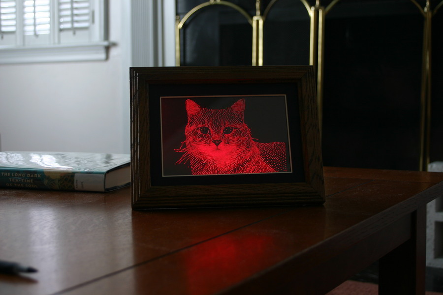
The subject today is called Marie. She's one of my two cats.
This image has 4600 dots in a 3.5x5" area of a 5x7" piece of plexiglass. The dots are drilled 0.004" (.1mm) into a 0.089" (2.3mm) piece of plexiglass, a process which takes about 20 minutes. In ambient light, the dots are barely visible. In this image, the dots are lit by 16 red LEDs (about 3/4W total power).
The input image was manipulated by hand to remove the background, increase the contrast, and to re-add whiskers that were removed with the background. With current versions of stippler, the contrast overload might be overdone---in previous versions, when the initial dot positions weren't chosen as well, the output image was not nearly contrasty enough.


You'll notice that the image is backwards. The viewing side is the undrilled side, because the drills create small cones which direct light out of the plexiglass towards the viewer. I failed to take this into account, but I should have known better.
The LEDs are run from a Micrel 2570 boost-mode switching power supply. I use it in a constant-current configuration, to give 20mA per string of LEDs. I've run it from a PC power supply's +5V, and from two partially-discharged AA batteries (2.5v). The brightness appeared identical in both cases, and the sense voltage measured close to 220mV both ways. With 3 LEDs the VOUT voltage measured around 7V.
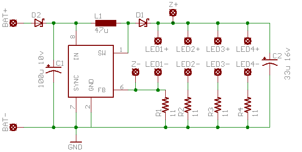
The confusingly-labeled Z+ and Z- pads have a 12.0V 1W zener wired between them, with the cathode at Z+. Without this diode, the board could fail if the string of LEDs used for current-limiting becomes disconnected: FB is pulled down to GND through R1, and the MIC2570 goes into continuous boost until it either reaches the current limit or the voltage rating of the output capacitor (16V) is exceeded. Tantalum capacitor datasheets all warn that when the voltage rating is exceeded, the capacitor may explode! Needless to say, I didn't want to test this. In normal operation, the Z diode doesn't conduct.
The 12.0V value was chosen to be above the maximum drop across 4 LEDs (4 * Vf_led <= 4 * 2.8V = 11.2V) and below the voltage rating of the output capacitor (16V). Plus, a 12.0V zener was available.
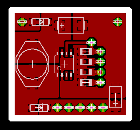
The input diode will probably be removed from the next iteration of the board. While it's nice to be protected against the wrong input polarity (I recently made a polarity mistake and I'm lucky I didn't fry my laptop's parallel port in the process) the ~.4V drop means an almost 15% decrease in efficiency when powered from 2 AA cells at 3V
Website Copyright © 2004-2024 Jeff Epler